
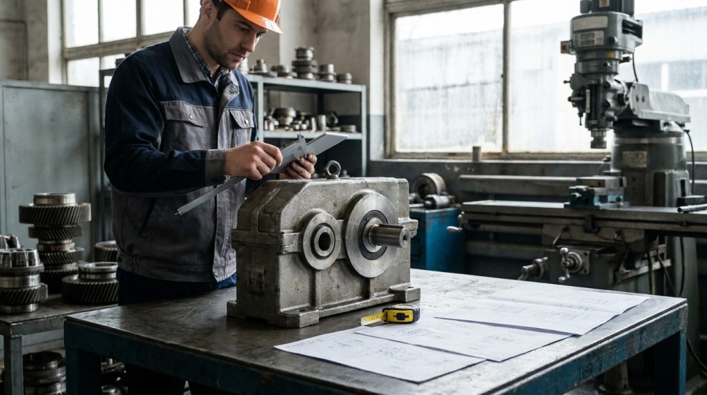
Understanding Industrial Gearbox Sizing: A Comprehensive Guide for Optimal Performance
Choosing the correct industrial gearbox is a critical decision that directly impacts the efficiency, longevity, and reliability of your machinery. An undersized gearbox can lead to premature failure, costly downtime, and compromised production, while an oversized unit represents an unnecessary capital expenditure. This comprehensive guide, crafted for plant managers, maintenance professionals, industrial engineers, manufacturers, agricultural operators, and equipment buyers, will walk you through the essential steps to properly size an industrial gearbox for your specific application. Based in Coldwater, Michigan, CEM Industrial Supply is your trusted partner for all your industrial gearbox needs, from expert selection to comprehensive repair and rebuilding services.
When considering the optimal sizing of an industrial gearbox for your application, it’s also beneficial to explore related topics that can enhance your understanding of industrial systems. For instance, you might find valuable insights in the article on crawl space encapsulation services, which discusses how proper environmental management can impact the longevity and efficiency of industrial equipment, including gearboxes. Understanding these interconnected aspects can lead to better decision-making in your industrial operations.
Critical Factors in Gearbox Sizing Calculations
Properly sizing an industrial gearbox requires a thorough understanding of the operational demands it will face. This isn’t a one-size-fits-all scenario; each application presents unique challenges. The following factors are paramount and must be meticulously assessed to ensure your selected gearbox will perform reliably and efficiently.
Load Type and Magnitude
The nature and intensity of the load are primary determinants in gearbox sizing. Different load types exert varying stresses on gear teeth and bearings.
Steady Loads
Steady loads, also known as uniform loads, are characterized by consistent torque and speed. Examples include conveyors moving uniform material, mixers with smooth operation, and pumps handling non-viscous fluids at constant flow. These loads are generally the least demanding on a gearbox.
Shock Loads
Shock loads involve sudden, intermittent application of high torque. This can occur in applications like reciprocating compressors, crushers, hammer mills, and material handling systems where materials are frequently dropped or impacted. Gearboxes designed for shock loads require robust construction, larger safety factors, and often specialized gear designs to withstand these transient forces.
Variable Loads
Variable loads fluctuate in magnitude over time. This could be a crane hoisting varying weights, a variable-speed drive controlling a fan, or a machine tool cutting materials of inconsistent hardness. Sizing for variable loads requires considering the peak torque experienced during operation, as well as the duration and frequency of these peaks.
Inertial Loads
Inertial loads are generated by accelerating or decelerating masses. Applications involving flywheels, large rotating drums, or heavy reciprocating masses fall into this category. The gearbox must be capable of handling the torque required to overcome inertia during startup and the braking torque during deceleration. This often necessitates a larger frame size or a higher service factor than might be indicated by the steady-state running torque alone.
Speed and Torque Requirements
The input and output speeds, along with the required output torque, form the core of the sizing calculation.
Input Speed (RPM)
The speed at which the prime mover (e.g., electric motor, engine) rotates is your input speed. This is typically expressed in revolutions per minute (RPM). Knowing this value precisely is crucial for determining the gear ratio needed and the resulting output speed.
Output Speed (RPM)
The desired speed of the driven equipment dictates the output speed requirement. This might be a fixed speed or a variable speed range. The difference between the input and output speed determines the necessary gear ratio.
Required Output Torque (Nm or lb-in)
This is the most critical parameter. It represents the rotational force the gearbox must deliver to the driven equipment. Torque is calculated based on the load’s resistance to motion.
- Calculation for Torque:
- Torque (T) = (Horsepower (HP) * 5252) / Speed (RPM) (using Imperial units)
- Torque (T) = (Power (kW) * 9549) / Speed (RPM) (using Metric units)
It’s essential to calculate the peak torque the system will experience, not just the average running torque, especially for applications with shock or variable loads.
Duty Cycle and Operating Hours
The frequency and duration of gearbox operation significantly influence its thermal capacity and wear characteristics.
Continuous Duty
Gearboxes operating continuously for extended periods (e.g., 24/7 in a manufacturing plant) require robust thermal management. Overheating is a major cause of lubricant degradation and premature bearing/seal failure.
Intermittent Duty
Applications that run for shorter, defined periods, with significant rest intervals, place less thermal stress on the gearbox. However, the torque requirements during operation are still critical.
Frequent Start/Stop Cycles
Gearboxes subjected to frequent starting and stopping will experience higher stress during each acceleration and deceleration phase. This can be more demanding than continuous operation at a steady load.
Environmental Conditions
The environment in which the gearbox operates can significantly impact its performance and lifespan.
Temperature
Extreme ambient temperatures (hot or cold) can affect lubricant viscosity and cooling efficiency. High operating temperatures can accelerate lubricant breakdown and material fatigue. Cold temperatures can increase starting torque requirements and affect lubrication flow.
Contamination (Dust, Water, Chemicals)
The presence of dust, moisture, corrosive chemicals, or other contaminants necessitates appropriate sealing and enclosure designs (e.g., IP ratings) to prevent ingress into the gearbox. Contamination can lead to accelerated wear of gears and bearings, and lubricant degradation.
Altitude
At higher altitudes, the reduced air density can impact the cooling efficiency of standard gearboxes. Special considerations for heat dissipation might be required.
Prime Mover and Driven Equipment Characteristics
Understanding the prime mover (e.g., motor type) and the driven equipment’s operational nuances is also important.
Motor Type and Starting Characteristics
Electric motors have different starting torque capabilities. Direct-on-line (DOL) starting typically provides higher starting torque than variable frequency drive (VFD) controlled motors, which can influence acceleration torque calculations.
Driven Equipment Inertia
As mentioned earlier, the inertia of the driven load directly impacts the acceleration and deceleration torque requirements.
Calculating Essential Gearbox Parameters
Once you have a clear understanding of your application’s demands, you can begin calculating the specific parameters needed to select the correct gearbox.
Gear Ratio Determination
The gear ratio is the fundamental relationship between the input speed and the output speed.
- Formula: Gear Ratio (GR) = Input Speed (RPM) / Output Speed (RPM)
A higher gear ratio means a lower output speed and a higher output torque (assuming 100% efficiency). For example, a 10:1 gear ratio means the output shaft will rotate 1/10th the speed of the input shaft.
Service Factor Application
The service factor (SF) is a multiplier used to account for variations in load, duty cycle, and operating conditions that are not precisely accounted for in basic torque calculations. It essentially adds a safety margin.
- How to Use: Multiply your calculated required torque by the appropriate service factor. The result is the minimum torque capacity the gearbox must possess.
- **Required Torque (with SF) = Calculated Torque * Service Factor**
Service factors are typically provided by gearbox manufacturers in tables and are categorized based on load types and duty cycles. For instance, a steady load on a continuous duty cycle might have an SF of 1.0, while a shock load with frequent starts might require an SF of 2.0 or higher. Always consult the manufacturer’s specific service factor tables.
Thermal Capacity Considerations
While torque is crucial for mechanical strength, thermal capacity is vital for preventing overheating and lubricant breakdown.
Heat Generation Sources
Heat is generated in a gearbox primarily through:
- Gear friction
- Bearing friction
- Seal friction
- Viscous shear within the lubricant
Heat Dissipation
Heat is dissipated through:
- Conduction through the gearbox housing
- Convection from the housing surface to the ambient air
- Radiation from the housing surface
Thermal Rating
Gearboxes are rated for their thermal capacity in terms of power. This rating indicates the maximum power that can be transmitted continuously under specific ambient conditions without the lubricant temperature exceeding a safe limit (typically around 90-100°C for most mineral oils).
If your application’s required power transmission exceeds the thermal rating of a gearbox that meets your torque requirements, you will need to:
- Select a larger frame size gearbox (which usually has better heat dissipation).
- Incorporate external cooling methods like oil coolers, fans, or forced lubrication systems.
- Reduce the ambient operating temperature if possible.
Understanding Gearbox Types and Their Suitability
Different gearbox configurations are designed for specific performance characteristics and applications. Choosing the right type is as important as sizing correctly.
Spur Gearboxes
Spur gearboxes are the simplest and most common type. They feature straight teeth parallel to the axis of rotation.
- Pros: High efficiency (up to 98%), simple design, cost-effective.
- Cons: Can be noisy at high speeds, not ideal for high thrust loads.
- Applications: Conveyors, general industrial machinery, pumps.
Helical Gearboxes
Helical gears have teeth cut at an angle to the axis of rotation.
- Pros: Quieter operation than spur gears, higher load-carrying capacity, suitable for higher speeds.
- Cons: Produce axial thrust loads that must be managed by bearings.
- Applications: Machine tools, high-speed applications, heavy-duty conveyors.
Bevel Gearboxes
Bevel gears are used to transmit power between shafts that intersect at an angle, typically 90 degrees.
- Pros: Can change the direction of rotation, compact design for right-angle drives.
- Cons: Lower efficiency than spur or helical gears, can generate significant thrust loads.
- Applications: Mixers, agricultural machinery, applications requiring a 90-degree power transition.
Worm Gearboxes
Worm gearboxes use a screw-like worm meshing with a worm wheel.
- Pros: High gear reduction ratios in a single stage, self-locking capability (in some configurations), quiet operation.
- Cons: Lower efficiency (can be as low as 50-80% depending on ratio and lubrication), generate significant heat.
- Applications: Lifts, hoists, conveyors, applications requiring large reduction ratios and/or self-locking.
Planetary Gearboxes
Planetary gearboxes offer a compact design with high torque density and concentric input/output shafts.
- Pros: High torque capacity in a small package, high efficiency, ability to handle shock loads, can achieve very high reduction ratios.
- Cons: More complex design, higher cost.
- Applications: Robotics, automation, heavy-duty material handling, high-performance industrial equipment.
Selecting the Right Lubricant
The lubricant is the lifeblood of a gearbox. Proper lubrication is critical for reducing friction, dissipating heat, and preventing wear.
Lubricant Types
- Mineral Oils: Common for general-purpose applications and moderate temperatures.
- Synthetic Oils: Offer superior performance at extreme temperatures (both high and low), better thermal stability, and longer drain intervals. They are often recommended for high-speed, high-load, or high-temperature applications.
- Greases: Used in some sealed-for-life gearboxes or specific bearing applications within a gearbox.
Viscosity
Viscosity is a lubricant’s resistance to flow. It is critical for ensuring proper film formation between moving parts. Viscosity is typically specified using the ISO VG (International Organization for Standardization Viscosity Grade) system. The correct viscosity depends on the operating temperature and speed of the gearbox.
Additives
Many industrial gearbox lubricants contain additives to enhance performance, such as:
- Extreme Pressure (EP) Additives: For high-load applications to prevent metal-to-metal contact.
- Anti-wear Additives: To protect gears and bearings from surface damage.
- Antioxidants: To prevent lubricant degradation at high temperatures.
- Rust and Corrosion Inhibitors: To protect internal components.
Always consult the gearbox manufacturer’s recommendations for the appropriate lubricant type, viscosity, and change intervals.
Troubleshooting Common Gearbox Issues
Even with proper sizing, industrial gearboxes can encounter problems. Early detection and resolution of issues can prevent minor problems from becoming catastrophic failures.
Identifying Symptoms of Failure
Be vigilant for these common indicators of gearbox distress:
- Unusual Noises: Grinding, whining, knocking, or rattling sounds can indicate gear wear, bearing damage, or misalignment.
- Excessive Heat: A gearbox that is significantly hotter than normal suggests lubrication issues, overload, or thermal capacity problems.
- Vibration: Increased vibration levels can point to unbalanced components, bearing wear, or misalignment.
- Oil Leaks: Leaks can lead to lubricant loss, contaminating the environment, and insufficient lubrication.
- Reduced Performance: A noticeable decrease in output speed or torque can indicate internal damage or excessive friction.
- Visible Damage: Metal particles in the oil, chipped or broken gear teeth, or worn bearing races.
Common Causes and Solutions
- Overloading:
- Cause: Application load exceeds gearbox torque capacity or thermal rating.
- Solution: Re-evaluate sizing, verify load calculations, check for binding in the driven equipment. If necessary, consider a larger gearbox or external cooling.
- Lubrication Issues:
- Cause: Incorrect lubricant type, insufficient lubricant level, contaminated lubricant, or improper lubricant viscosity.
- Solution: Verify lubricant specifications, check fill levels regularly, implement strict contamination control procedures, and adhere to recommended change intervals.
- Misalignment:
- Cause: Improper installation between the prime mover and gearbox, or between the gearbox and driven equipment.
- Solution: Ensure precise alignment during installation using dial indicators or laser alignment tools. Regular checks are recommended.
- Bearing Failure:
- Cause: Overloading, contamination, insufficient lubrication, improper installation, or normal wear and tear.
- Solution: Replace bearings with correct specifications. Address the root cause to prevent recurrence.
- Gear Wear/Damage:
- Cause: Overloading, shock loads, contamination, incorrect lubrication, or material defects.
- Solution: Replace damaged gears. Investigate the cause, which often involves reviewing load calculations, lubrication practices, and operating conditions.
When considering the optimal performance of your machinery, understanding how to size an industrial gearbox for your application is crucial. For those looking to enhance their operational efficiency, it can be beneficial to explore related topics such as selecting the right contractors for your projects. A helpful resource on this subject can be found in the article about choosing top general contractors, which provides essential tips that can aid in ensuring your equipment is installed and maintained properly.
Maintenance and Longevity of Your Industrial Gearbox
Proactive maintenance is the key to maximizing the lifespan and reliability of your industrial gearbox. A well-maintained gearbox operates efficiently, reduces energy consumption, and minimizes unplanned downtime.
Routine Inspections and Checks
Establish a regular inspection schedule, typically daily or weekly, for the following:
- Visual Inspection: Look for oil leaks, unusual noises, vibrations, or external damage.
- Oil Level Check: Ensure the oil level is within the manufacturer’s specified range.
- Temperature Monitoring: Use an infrared thermometer to check the gearbox housing temperature. Any significant increase should be investigated.
- Listening for Abnormal Sounds: Pay attention to any changes in the gearbox’s operating sound.
Scheduled Maintenance Activities
Beyond routine checks, implement a scheduled maintenance program:
- Oil Sampling and Analysis: Periodically take oil samples and send them for laboratory analysis. This can detect early signs of wear, contamination, and lubricant degradation, often revealing problems before they become visible.
- Oil Changes: Adhere to the manufacturer’s recommended oil change intervals. These intervals are based on operating hours, temperature, and load conditions.
- Filter Replacement (if applicable): If your gearbox has an oil filter, replace it according to the manufacturer’s recommendations.
- Seal Inspection and Replacement: Worn or damaged seals can lead to leaks and contamination. Inspect seals during oil changes and replace them as needed.
- Gasket Inspection: Check for any signs of leakage around gaskets and replace them if necessary.
- Bolt Tightness: Periodically check the tightness of all mounting bolts and fasteners.
- Mounting and Alignment Verification: Re-verify the mounting and alignment of the gearbox, especially after significant operational events or if vibrations are detected.
Best Practices for Extended Gearbox Life
- Operate Within Design Limits: Never exceed the gearbox’s rated torque, speed, or thermal capacity.
- Ensure Proper Ventilation: Allow adequate airflow around the gearbox for effective cooling.
- Protect from Harsh Environments: Use appropriate enclosures, seals, and coatings if operating in corrosive or dusty environments.
- Use High-Quality Lubricants: Always use the lubricant type and grade recommended by the manufacturer.
- Implement a Strict Contamination Control Program: Prevent dirt, water, and other contaminants from entering the gearbox.
- Train Personnel: Ensure maintenance staff are properly trained in gearbox inspection, maintenance, and troubleshooting.
When considering the optimal performance of machinery, understanding how to size an industrial gearbox for your application is crucial. A related article that delves deeper into the selection process and factors to consider can be found at CEM Industrial Supply. This resource offers valuable insights that can help you make informed decisions about your equipment needs, ensuring efficiency and reliability in your operations.
Safety Considerations for Industrial Gearboxes
Working with industrial gearboxes involves inherent risks. Adhering to strict safety protocols is paramount.
Personal Protective Equipment (PPE)
Always wear appropriate PPE when working on or around industrial gearboxes:
- Safety Glasses: To protect against flying debris or splashes.
- Gloves: To protect hands from hot surfaces, sharp edges, and lubricants.
- Safety Shoes: To protect feet from falling objects and provide slip resistance.
- Hearing Protection: If operating in a noisy environment.
Lockout/Tagout Procedures
Before any maintenance or inspection work begins, ensure that:
- Power is Disconnected: The prime mover driving the gearbox is completely de-energized.
- Lockout/Tagout (LOTO) Procedures are Followed: Apply locks and tags to the energy isolating devices to prevent accidental re-energization.
- Stored Energy is Released: Ensure any stored mechanical or hydraulic energy is safely discharged.
Hot Surfaces and Rotating Machinery
- Allow Cooling: Gearboxes can reach high operating temperatures. Always allow them to cool sufficiently before touching.
- Guard Rotating Parts: Ensure all guards for rotating shafts, gears, and couplings are in place and secure. Never bypass safety guards.
Safe Lifting and Handling
Industrial gearboxes can be heavy. Use appropriate lifting equipment and follow safe lifting practices:
- Use Cranes, Hoists, or Forklifts: For lifting heavy gearboxes.
- Securely Attach Lifting Points: Ensure lifting slings or chains are properly attached to designated lifting points.
- Clear the Area: Ensure the area where the gearbox is being moved is clear of personnel.
Partner with CEM Industrial Supply for Your Gearbox Needs
Selecting the correct industrial gearbox for your application is a complex but crucial task. CEM Industrial Supply, based right here in Coldwater, Michigan, is dedicated to providing manufacturers, agricultural operators, and industrial facilities with the expertise and high-quality products they need. Our team understands the intricacies of gearbox sizing, application requirements, and the importance of reliability in your operations.
Whether you are designing a new system, upgrading existing equipment, or facing a breakdown, our experienced professionals can assist you. We offer a wide range of industrial gearboxes from leading manufacturers, and our technical team is adept at helping you navigate the selection process.
If your industrial gearbox has experienced wear, damage, or simply needs a comprehensive overhaul, look no further than CEM Industrial Supply for expert industrial gearbox repair and rebuilding services. We can extend the life of your existing equipment and provide cost-effective solutions. For unique challenges or specific performance requirements, we can also assist with custom gearbox solutions.
Don’t let an improperly sized or failing gearbox compromise your production. Contact CEM Industrial Supply today to discuss your industrial gearbox requirements. Our team is ready to provide the solutions and support you need to keep your operations running smoothly and efficiently.
Frequently Asked Questions (FAQs)
Q1: How do I calculate the required torque for my application?
A1: Torque is calculated based on the power transmitted and the speed of rotation. The formula is:
- In Imperial units: Torque (lb-in) = (Horsepower (HP) * 63025) / Speed (RPM)
- In Metric units: Torque (Nm) = (Power (kW) * 9549) / Speed (RPM)
It’s crucial to consider the peak torque your system will experience, especially if there are shock or variable loads, and to apply the appropriate service factor.
Q2: What is a service factor, and why is it important?
A2: The service factor (SF) is a multiplier that accounts for variations in load, operating conditions, and duty cycles not precisely captured in basic torque calculations. It’s a safety margin. You multiply your calculated required torque by the service factor to determine the minimum torque capacity your gearbox must possess. Manufacturers provide service factor tables based on load type and operating conditions.
Q3: How does temperature affect gearbox sizing and operation?
A3: Temperature is critical for both thermal capacity and lubricant performance. High operating temperatures can degrade lubricants and cause premature wear. Gearboxes have a thermal rating, indicating the maximum power they can transmit continuously without overheating. If your application’s thermal demands exceed this rating, you may need a larger gearbox, external cooling, or a different lubricant. Cold temperatures can increase starting torque and affect lubricant flow.
Q4: What’s the difference between spur and helical gearboxes?
A4: Spur gearboxes have straight teeth parallel to the shaft and are simple, efficient, and cost-effective but can be noisy. Helical gearboxes have teeth cut at an angle, making them quieter, capable of higher load capacities, and suitable for higher speeds, but they generate axial thrust loads that need to be managed.
Q5: How often should I change the oil in my industrial gearbox?
A5: Oil change intervals vary significantly based on the gearbox type, operating conditions (load, temperature, duty cycle), and the lubricant used. Always refer to the gearbox manufacturer’s recommendations. Regular oil analysis can help determine the optimal oil change intervals and detect potential problems early.