
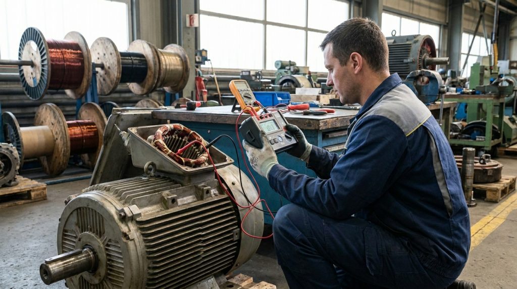
Understanding Motor Insulation Resistance Testing: A Guide for Industrial Professionals
In the demanding world of industrial operations, reliable machinery is the backbone of productivity. Electric motors, the unsung heroes powering countless processes, are no exception. However, even the most robust electric motors are susceptible to degradation over time, with insulation failure being a primary culprit for costly downtime and catastrophic failures. This is where motor insulation resistance testing, often referred to as megger testing, becomes an indispensable tool for industrial maintenance technicians, plant managers, electricians, and equipment owners alike. Understanding this critical diagnostic procedure can significantly extend motor lifespan, prevent unexpected breakdowns, and ensure operational safety.
At CEM Industrial Supply in Coldwater, Michigan, we understand the vital role electric motors play in your operations. Our expertise extends not only to providing high-quality industrial supplies but also to offering expert electric motor repair and diagnostic services. This article delves deep into the intricacies of motor insulation resistance testing, equipping you with the knowledge to effectively assess and maintain the health of your electric motors.
Motor insulation resistance testing is a critical procedure for ensuring the reliability and safety of electrical motors. For those interested in understanding the broader context of electrical tools and their applications, you might find the article on concrete drilling techniques particularly insightful. It explains the differences between hammer drills and rotary hammers, which can be essential for professionals working in construction and electrical installations. To learn more about these tools and their functionalities, visit the article here: Hammer Drill vs. Rotary Hammer: Concrete Drilling Explained.
The Fundamental Principles of Motor Insulation Resistance
Electric motors operate by converting electrical energy into mechanical energy, a process facilitated by carefully designed electromagnetic fields. At the core of this conversion are the motor windings, typically made of copper or aluminum wire. These windings are insulated to prevent them from short-circuiting with each other or with the motor’s metallic frame. This insulation is crucial for the proper functioning and safety of the motor.
The insulation material, often a specialized varnish or epoxy coating applied to the wires, is designed to withstand the operational stresses of heat, vibration, and electrical potential. However, over time, this insulation can degrade due to various factors, including:
- Heat: High operating temperatures accelerate the aging process of insulation materials.
- Moisture: Water and humidity can penetrate insulation, reducing its dielectric strength.
- Contamination: Dust, oil, and chemicals can act as conductive paths, compromising insulation integrity.
- Mechanical Stress: Vibration and physical shock can lead to cracks or abrasions in the insulation.
- Voltage Surges: Electrical transients can stress and eventually break down insulation.
When insulation degrades, its ability to resist the flow of electrical current diminishes. This leakage current, though often small initially, can grow over time, leading to increased heat generation, reduced efficiency, and ultimately, motor failure.
What is Insulation Resistance?
Insulation resistance is a measure of how well the insulating materials within an electric motor are preventing electrical current from “leaking” between the motor windings and the motor frame, or between different sets of windings. A high insulation resistance value indicates good insulating quality, meaning very little current is escaping. Conversely, a low insulation resistance value suggests that the insulation is compromised, and significant leakage current is flowing.
This leakage current is problematic for several reasons:
- Efficiency Loss: The leaked current represents wasted energy, contributing to higher electricity bills.
- Heat Generation: Leakage current flowing through the degraded insulation can generate localized heat, further accelerating insulation deterioration and potentially damaging the windings.
- Short Circuits: In severe cases, insulation failure can lead to direct short circuits, causing immediate motor burnout and potentially damaging other electrical components.
- Safety Hazards: A compromised insulation system can create a shock hazard for personnel working around the motor.
The Role and Application of Motor Insulation Resistance Testing
Motor insulation resistance testing is a non-destructive diagnostic procedure used to assess the condition of the insulation system in electric motors. It involves applying a specific DC voltage to the motor’s windings and measuring the resulting resistance to ground. This test provides a quantitative value that indicates the overall health of the insulation.
Why Perform Insulation Resistance Testing?
Regular insulation resistance testing offers numerous benefits for industrial facilities:
- Predictive Maintenance: By tracking insulation resistance values over time, maintenance teams can identify gradual degradation before it leads to a failure. This allows for planned maintenance, minimizing unexpected downtime.
- Failure Prevention: Early detection of low insulation resistance can prompt corrective actions, such as cleaning, drying, or even rewinding the motor, preventing catastrophic failure.
- Troubleshooting: When a motor exhibits unusual behavior, such as overheating or tripping breakers, insulation resistance testing can quickly determine if insulation failure is the root cause.
- Asset Management: Understanding the condition of your motor fleet through regular testing helps in prioritizing maintenance efforts and making informed decisions about motor replacement.
- Safety Assurance: Ensuring that motor insulation is in good condition is crucial for preventing electrical hazards and protecting personnel.
When to Perform Insulation Resistance Testing
Several scenarios warrant insulation resistance testing:
- Routine Maintenance: As part of a scheduled preventive maintenance program, typically performed annually or semi-annually depending on the motor’s criticality and operating environment.
- New Motor Installation: To verify the integrity of the insulation before putting a new motor into service.
- Post-Repair or Rewind: To confirm that repairs or rewinding procedures have restored the insulation to acceptable levels.
- After Exposure to Adverse Conditions: Following events like flooding, significant contamination, or severe electrical surges.
- When Performance Issues Arise: If a motor shows signs of overheating, reduced output, or intermittent tripping.
- Before Extended Storage: To ensure insulation integrity for motors that will be stored for extended periods.
Performing Motor Insulation Resistance Tests: Practical Steps and Considerations
Executing an insulation resistance test requires specific equipment and adherence to proper procedures to ensure accurate results and personal safety.
Essential Equipment: The Insulation Resistance Tester (Megger)
An insulation resistance tester, commonly known as a “megger,” is a specialized instrument designed to apply a high DC voltage and measure the resulting low current. These testers are available in various voltage ratings, and the appropriate tester must be selected based on the motor’s voltage rating.
- Voltage Selection: For most industrial motors, testers with voltages of 500 VDC, 1000 VDC, or even higher (for higher voltage motors) are used. Refer to motor manufacturer recommendations or industry standards (e.g., IEEE, NETA) for specific voltage guidelines. A general rule of thumb is to use a test voltage that is approximately twice the rated voltage of the motor, plus 1000V, though specific standards should always be consulted.
- Digital vs. Analog: Modern digital meggers offer precise readings and often include data logging capabilities, while older analog models are still functional.
Step-by-Step Testing Procedure
Always prioritize safety before commencing any electrical testing.
Safety Precautions:
- De-energize and Lockout/Tagout: Absolutely critical. Ensure the motor is completely disconnected from the power source. Apply lockout and tagout procedures to prevent accidental re-energization.
- Verify Zero Energy State: Use a reliable voltage tester to confirm that no voltage is present at the motor terminals.
- Discharge Capacitance: Motor windings can store a significant electrical charge. After testing, it is essential to safely discharge this stored energy by connecting the motor terminals to ground.
- Personal Protective Equipment (PPE): Wear appropriate PPE, including insulated gloves, safety glasses, and flame-resistant clothing.
- Understand Your Equipment: Familiarize yourself with the operation of your specific insulation resistance tester.
- Environmental Conditions: Perform tests in a dry environment. High humidity can lead to inaccurate, artificially low readings.
Testing Steps:
- Access Motor Terminals: Open the motor’s terminal box or junction box.
- Disconnect Load (If Possible): For a more accurate reading of the motor’s insulation only, disconnect the motor from the load and any associated control wiring. If this is not feasible, be aware that readings may be affected by external circuits.
- Clean Terminals: Ensure the motor terminals are clean and free from dirt, grease, or corrosion.
- Connect the Megger:
- Connect the “Line” or “Positive (+)” lead of the megger to one of the motor’s winding leads (e.g., T1).
- Connect the “Earth” or “Ground (-)” lead of the megger to the motor’s frame (ground connection).
- For three-phase motors, you will typically perform three separate tests: T1 to Ground, T2 to Ground, and T3 to Ground. Alternatively, you can test between windings (e.g., T1 to T2, T1 to T3, T2 to T3) to assess winding-to-winding insulation.
- Apply Test Voltage: Turn on the megger and apply the selected DC test voltage for the specified duration (typically 60 seconds). Many modern testers have a “spot reading” or “absorption ratio” function that automates this.
- Record Readings: Note the insulation resistance value displayed by the megger. For spot readings, record the value after the 60-second application. For more advanced analysis, record readings at 15 seconds, 30 seconds, and 60 seconds.
- Discharge the Motor: After taking the readings, turn off the megger and disconnect the leads. Crucially, connect the motor terminals back to ground for a few minutes to discharge any stored electrical energy. Do not touch the terminals during this discharge period.
- Repeat for Other Windings: If testing phases individually, repeat steps 4-7 for T2 to Ground and T3 to Ground. If testing winding-to-winding, ensure all other windings are grounded.
Interpreting Insulation Resistance Readings
Interpreting the raw numbers from a megger is where experience and knowledge come into play. Simple pass/fail criteria are often insufficient for effective predictive maintenance.
Basic Interpretation Guidelines
- High Readings: A very high insulation resistance (e.g., several Gigaohms, or GO) generally indicates excellent insulation condition.
- Low Readings: Consistently low readings suggest a problem.
- Moderate Readings: These can be ambiguous and require further analysis.
Industry Standards and Guidelines
Various organizations provide recommended minimum insulation resistance values. Two common benchmarks are:
- IEEE Standards: The Institute of Electrical and Electronics Engineers (IEEE) publishes standards for electrical equipment. For motors, IEEE Standard 43 is a relevant reference. A common rule of thumb derived from IEEE recommendations is:
- Minimum Acceptable Insulation Resistance: 1 Megohm (MΩ) per kilovolt (kV) of rated voltage, plus 1 MΩ.
- Example: For a 480V motor (0.48 kV), the minimum would be (0.48 * 1) + 1 = 1.48 MΩ.
- Example: For a 4160V motor (4.16 kV), the minimum would be (4.16 * 1) + 1 = 5.16 MΩ.
- PI (Polarization Index) and DAR (Dielectric Absorption Ratio) Tests: These are more sophisticated methods that involve taking multiple readings over time.
- Polarization Index (PI): Calculated as the ratio of insulation resistance measured at 10 minutes to the insulation resistance measured at 1 minute (R₁₀min / R₁min). A PI test is typically performed using a 10-minute test duration.
- Good: PI ≥ 3.0
- Questionable: 2.0 ≤ PI < 3.0
- Poor: PI < 2.0
- Benefit: The PI test is less sensitive to temperature and humidity variations than a spot reading and helps identify insulation that is deteriorating internally.
- Dielectric Absorption Ratio (DAR): Calculated as the ratio of insulation resistance measured at 60 seconds to the insulation resistance measured at 30 seconds (R₆₀sec / R₃₀sec).
- Good: DAR ≥ 1.5
- Questionable: 1.25 ≤ DAR < 1.5
- Poor: DAR < 1.25
- Benefit: The DAR provides a quicker assessment, often sufficient for routine checks, and is also useful for evaluating insulation condition.
Factors Affecting Readings
Several external factors can influence insulation resistance readings:
- Temperature: Insulation resistance generally decreases as temperature increases. If readings are taken at different temperatures, they may not be directly comparable. It’s best practice to correct readings to a standard temperature, typically 40°C (104°F). Online calculators or tables are available for this correction.
- Humidity: High humidity can allow surface moisture to create conductive paths, artificially lowering resistance readings.
- Contamination: Dust, oil, and other contaminants on the motor terminals or within the terminal box can bridge insulation and cause low readings.
- Motor Size and Age: Larger motors with more windings may naturally have lower resistance values than smaller ones. Older motors, due to insulation aging, will also tend to have lower readings.
Troubleshooting Common Insulation Resistance Issues
When insulation resistance tests reveal problems, a systematic approach is needed to pinpoint the cause.
Common Causes of Low Insulation Resistance
- Moisture Ingress: Water or high humidity has penetrated the insulation. This is especially common in motors operating in damp environments or those that have been exposed to washdowns.
- Contamination: Dust, dirt, oil, or chemical residues have accumulated on the windings or within the terminal box, creating conductive paths.
- Damaged Insulation: Physical abrasion, cuts, or cracks in the insulation due to vibration, impact, or improper handling.
- Overheating: Prolonged operation at excessively high temperatures accelerates insulation breakdown.
- Voltage Spikes/Surges: Electrical transients from switching operations or lightning strikes can weaken insulation.
- Winding Short Circuits: Direct shorts between turns within a winding or between windings themselves.
- Ground Faults: A winding making direct contact with the motor frame.
- Aging Insulation: Natural degradation of insulation materials over the motor’s lifespan.
Troubleshooting Steps When Readings are Low
- Verify Test Procedure and Equipment: Double-check that the test was performed correctly, the megger is functioning properly, and the correct voltage was used.
- Check Environmental Conditions: Was the test performed in a dry, clean environment? High humidity or the presence of moisture will significantly impact readings.
- Inspect Motor Terminals and Terminal Box: Thoroughly clean the terminals and the inside of the terminal box. Look for any signs of corrosion, debris, or damage.
- Visual Inspection of Windings: If possible, visually inspect the motor windings for signs of charring, discoloration, or physical damage. This may require disassembling the motor.
- Perform Insulation Resistance Test After Cleaning/Drying: After cleaning and drying, repeat the insulation resistance test. If readings improve significantly, contamination or moisture was likely the primary issue.
- Differential Testing (Three-Phase Motors):
- Winding to Ground: Test each phase winding (T1, T2, T3) to ground. If one phase shows a significantly lower reading than the others, that phase may have a fault.
- Winding to Winding: Test between phases (T1 to T2, T1 to T3, T2 to T3) with all other windings grounded. Low readings here indicate insulation breakdown between windings.
- Consider Motor Temperature: If the motor was recently running, its windings will be hot, and insulation resistance will be lower. Allow the motor to cool before testing or correct readings to a standard temperature.
- Consult Motor Manufacturer Data: Refer to the motor’s nameplate and any accompanying documentation for specific recommended insulation resistance values and testing procedures.
- Seek Expert Assistance: If you are unable to identify the cause or the readings remain consistently low, it’s time to contact a professional electric motor repair service.
Advanced Testing Techniques and Motor Health Assessment
While spot readings and PI/DAR tests are valuable, more advanced techniques can provide deeper insights into motor health.
Surge Testing
Surge testing involves applying a high-voltage pulse to the windings and analyzing the resulting voltage waveforms. This technique is highly effective at detecting inter-turn shorts, which are often missed by traditional insulation resistance tests. A surge tester can identify minute weaknesses in the insulation between individual turns of wire.
Partial Discharge (PD) Testing
Partial discharge is a localized dielectric breakdown in an insulating material that does not completely bridge the electrodes. PD activity generates radio frequency signals that can be detected and analyzed. Monitoring PD activity over time can provide early warnings of insulation degradation before it leads to a complete breakdown.
Thermal Imaging
Infrared thermography can identify hot spots within a motor, which are often indicative of increased electrical resistance due to insulation problems, unbalanced windings, or bearing issues. While not a direct insulation resistance test, it complements other diagnostic methods.
For those interested in understanding the importance of motor insulation resistance testing, you might also find it helpful to explore a related article that discusses the durability of power tools on the job site. This article compares two popular brands, Milwaukee and DeWalt, and evaluates which tools are more reliable over time. You can read more about it in this insightful piece on power tool longevity. Understanding both motor insulation testing and tool durability can greatly enhance your knowledge of maintaining equipment effectively.
Preventing Insulation Degradation: Proactive Maintenance Strategies
The best approach to insulation resistance issues is prevention. Implementing robust maintenance strategies can significantly prolong the life of your electric motors.
Best Practices for Motor Insulation Maintenance
- Maintain a Clean Operating Environment: Regularly clean motors, their surroundings, and terminal boxes to prevent dust, dirt, and chemical buildup.
- Control Moisture and Humidity:
- Ensure adequate ventilation in motor rooms.
- Use space heaters for motors in damp or humid environments, especially during off-cycles.
- Prevent direct water spray or submersion during washdowns.
- Manage Operating Temperatures:
- Ensure motors are adequately sized for their load.
- Avoid overloading motors.
- Check cooling fan functionality and ensure air intake/outlets are clear.
- Monitor bearing condition, as worn bearings can increase motor load and temperature.
- Protect Against Voltage Surges:
- Install surge protection devices on power feeds to critical motors.
- Ensure proper grounding of all electrical equipment.
- Regular Lubrication: Properly lubricated bearings reduce friction and motor load, contributing to lower operating temperatures.
- Vibration Analysis: Address excessive motor vibration promptly, as it can lead to mechanical stress on insulation.
- Scheduled Insulation Resistance Testing: Implement a consistent schedule for insulation resistance testing, as outlined earlier. Track historical data to identify trends.
- Proper Motor Handling and Storage: When installing new motors or storing old ones, handle them carefully to avoid physical damage to insulation. Use appropriate storage conditions (dry, controlled temperature).
Choosing the Right Motor and Repair Services
When the time comes to replace a motor or repair an existing one, quality and expertise are paramount.
When to Repair vs. Replace
- Repair is often feasible and cost-effective when:
- The motor is relatively new or in good overall condition.
- The failure is due to minor insulation issues, bearing problems, or brush replacement (for DC motors).
- The motor is a specialized or custom unit, making replacement difficult or expensive.
- Replacement may be necessary when:
- The motor has suffered severe internal damage (e.g., burnt windings, damaged core).
- The motor is very old and showing signs of widespread material fatigue.
- Energy efficiency improvements make a new, more efficient motor a more economical choice over time.
- The cost of repair approaches or exceeds the cost of a new motor.
The Importance of Professional Electric Motor Repair
For any motor repair, especially those involving insulation, engaging a reputable service provider is crucial. CEM Industrial Supply partners with experienced technicians who understand the intricacies of motor construction and repair. Our electric motor repair services ensure that your motors are restored to optimal performance with quality parts and expert craftsmanship. This includes:
- Thorough Diagnostics: Utilizing advanced testing equipment to accurately diagnose the root cause of the failure.
- Quality Rewinding: Employing proper winding techniques and using high-grade insulation materials that meet or exceed original specifications.
- Precision Balancing: Ensuring rotors are precisely balanced to minimize vibration and prolong bearing life.
- Rigorous Testing: Performing comprehensive post-repair testing, including insulation resistance, surge testing, and operational tests, to guarantee reliability.
Frequently Asked Questions About Motor Insulation Resistance Testing
Q1: How often should I perform insulation resistance testing on my electric motors?
A1: The frequency of testing depends on the motor’s criticality, operating environment, and manufacturer recommendations. A common starting point is annually for critical motors and biennially for less critical ones. Tracking historical data will help you refine your testing schedule.
Q2: What is the difference between a spot reading and a PI or DAR test?
A2: A spot reading is a single measurement taken at a specific time. PI (Polarization Index) and DAR (Dielectric Absorption Ratio) tests involve taking multiple readings over a period (minutes for PI, seconds for DAR) and calculating ratios. These ratio tests provide a more comprehensive assessment of insulation health and are less sensitive to temperature and humidity fluctuations than spot readings.
Q3: My megger readings are low, but the motor seems to be running fine. Should I be concerned?
A3: Yes, you should be concerned. Low insulation resistance indicates that the insulation is degrading, even if it hasn’t yet caused a noticeable performance issue or failure. This is the perfect opportunity for proactive maintenance to prevent a more significant problem down the line.
Q4: Can I use a regular multimeter for insulation resistance testing?
A4: No. Standard multimeters typically have limited voltage outputs (e.g., 9V) and are not designed to apply the high DC voltages required for effective insulation resistance testing. Using a multimeter will not provide meaningful or accurate readings for this purpose. You need a dedicated insulation resistance tester (megger).
Q5: What are the risks of performing insulation resistance testing incorrectly?
A5: The primary risks are safety hazards, including electrical shock if the motor is not properly de-energized and locked out, and damage to the motor or the testing equipment if incorrect procedures or voltages are used. Always follow safety protocols and consult your equipment’s manual.
Conclusion: Protecting Your Industrial Assets with Smart Motor Maintenance
Motor insulation resistance testing is not just a routine maintenance task; it’s a critical diagnostic tool that safeguards your industrial operations from costly failures. By understanding the principles behind insulation resistance, the proper testing procedures, and the implications of the readings, you can significantly enhance the reliability and lifespan of your electric motors.
At CEM Industrial Supply, we are committed to supporting your maintenance efforts. Whether you need high-quality industrial supplies, expert electric motor repair, or reliable motor replacements, our team in Coldwater, Michigan, is here to help. Don’t wait for a breakdown to address your motor’s health.
Contact CEM Industrial Supply today for all your electric motor diagnostics, repair needs, and essential industrial supplies. Let us help you keep your operations running smoothly and efficiently. Visit cemindustrialsupply.com or call us to speak with one of our experts.