
Understanding Gear Reduction Ratio: The Engine of Industrial Performance
In the intricate world of industrial machinery, efficiency and precise control are paramount. At the heart of many systems, from the smallest conveyor belts to the most powerful manufacturing lines, lies a critical component: the gearbox. Specifically, the gear reduction ratio dictates the fundamental relationship between input speed and output torque, directly impacting the performance, capabilities, and energy consumption of equipment. For plant managers, maintenance professionals, and engineers across diverse sectors like manufacturing, agriculture, and material handling, a thorough understanding of gear reduction ratios is not just beneficial; it’s essential for optimizing operations, extending equipment lifespan, and making informed purchasing decisions. This article delves deep into the concept of gear reduction ratio, exploring its implications for speed, torque, and overall industrial performance, and how CEM Industrial Supply in Coldwater, Michigan, can be your trusted partner in gearbox solutions.
Understanding gear reduction ratios is essential for optimizing speed, torque, and overall performance in various applications. For those interested in enhancing their operational efficiency, you might find it beneficial to explore how effective jobsite delivery can impact your workflow. Check out this related article on how jobsite delivery saves you time and money by following this link: Jobsite Delivery Efficiency.
The Fundamental Principles of Gear Reduction
A gearbox is essentially a mechanical system designed to transmit power between a prime mover (like an electric motor) and a driven load. Its primary function is to modify the speed and torque characteristics of the prime mover to match the requirements of the application. The gear reduction ratio is the numerical factor that defines this modification.
How Gear Reduction Works: Gears in Motion
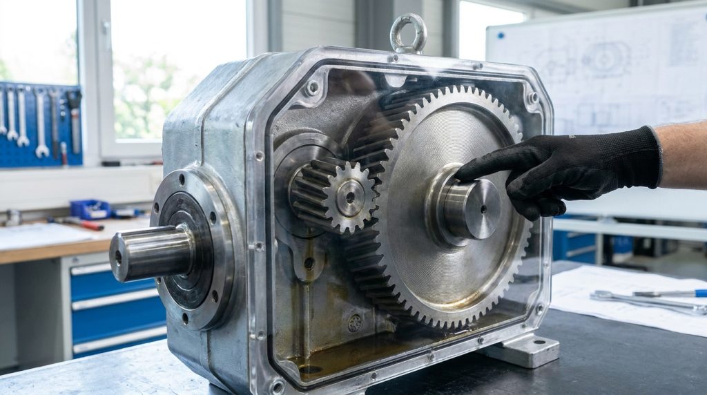
At its core, a gearbox utilizes a series of meshing gears to achieve speed reduction and torque multiplication. Gears are circular components with teeth that interlock. When two gears mesh, the rotation of one causes the other to rotate. The ratio of their sizes, specifically the number of teeth on each gear, determines how their speeds and torques are related.
Consider a simple gear train consisting of two meshing gears: a driving gear and a driven gear. If the driving gear has fewer teeth than the driven gear, it must rotate more times to complete one full rotation of the driven gear. This is the essence of speed reduction. Simultaneously, as speed is reduced, torque is increased. This inverse relationship is governed by the principle of conservation of energy, ignoring frictional losses.
Defining Gear Reduction Ratio: The Mathematical Relationship
The gear reduction ratio is mathematically defined as the ratio of the number of teeth on the driven gear to the number of teeth on the driving gear.
Gear Reduction Ratio (GRR) = Number of Teeth on Driven Gear / Number of Teeth on Driving Gear
Alternatively, it can be expressed as the ratio of the input speed to the output speed:
GRR = Input Speed (RPM) / Output Speed (RPM)
A ratio greater than 1 indicates a reduction in speed and an increase in torque. For example, a 10:1 gear reduction ratio means that for every 10 revolutions of the input shaft, the output shaft will complete 1 revolution. This also implies that the output torque will be, in theory, 10 times the input torque (minus losses). Conversely, a ratio less than 1 would represent a speed increase and torque decrease, often referred to as an overdrive. In the context of industrial machinery, gear reduction is almost always the desired outcome.
The Importance of Input and Output Speeds
The input speed is typically determined by the prime mover, most commonly an electric motor. Standard electric motors operate at specific synchronous speeds (e.g., 1800 RPM, 3600 RPM), which are influenced by the frequency of the electrical power supply and the number of poles in the motor. The desired output speed for a driven application, however, can vary significantly. A conveyor belt might need to move at a slow, controlled pace, while a high-speed packaging machine requires rapid movement. The gearbox, with its precisely engineered gear reduction ratio, bridges this gap.
Torque Multiplication: The Power Behind the Performance
While speed reduction is a direct consequence of gear reduction ratio, the more significant benefit in many industrial applications is torque multiplication. Torque is the rotational equivalent of force, representing the twisting or turning power of an object.
Understanding Torque and its Industrial Significance
In industrial settings, torque is critical for overcoming resistance. This resistance can come from:
- Inertia: Starting a heavy load from rest requires significant initial torque to overcome its inertia.
- Friction: Moving parts, materials, and environments all contribute to frictional forces that must be overcome.
- Load Demands: Pumping fluids, crushing materials, lifting heavy objects, or driving machinery all impose specific torque requirements.
Without sufficient torque, a machine will stall, fail to perform its intended function, or require an oversized and inefficient prime mover. The gearbox acts as a torque multiplier, allowing a smaller, more energy-efficient motor to drive a heavy load by providing the necessary rotational force.
Calculating Torque Output from Gear Reduction Ratio
The theoretical output torque of a gearbox is directly proportional to the input torque and the gear reduction ratio, with a factor accounting for efficiency losses.
**Theoretical Output Torque = Input Torque * Gear Reduction Ratio**
In reality, however, every mechanical system experiences some degree of energy loss due to friction between meshing gears, bearings, and seals. This is quantified by the gearbox’s efficiency rating.
**Actual Output Torque ≈ (Input Torque Gear Reduction Ratio) Efficiency**
For example, if a motor provides 100 lb-ft of torque at an input speed of 1800 RPM, and it’s connected to a gearbox with a 20:1 gear reduction ratio and 85% efficiency:
- Theoretical Output Torque = 100 lb-ft * 20 = 2000 lb-ft
- Actual Output Torque ≈ 2000 lb-ft * 0.85 = 1700 lb-ft
- Output Speed = 1800 RPM / 20 = 90 RPM
This demonstrates how a relatively small motor can generate substantial torque at a reduced speed, making it capable of driving heavy loads. The selection of the correct gear reduction ratio is therefore crucial for matching the torque requirements of the driven application to the capabilities of the prime mover and gearbox.
Types of Gearboxes and Their Ratio Capabilities
The gear reduction ratio is achieved through different gearbox designs, each suited for specific applications and capable of delivering a wide range of ratios.
Spur Gearboxes: Simplicity and Versatility
Spur gears are the most common type, featuring straight teeth parallel to the axis of rotation. They are simple to manufacture, cost-effective, and can achieve moderate gear reduction ratios in single stages. Multiple stages can be combined to achieve higher ratios.
- Applications: Conveyors, small machine tools, pumps, fans.
- Ratio Range: Typically up to 10:1 per stage, but higher ratios are achievable with multi-stage designs.
- Advantages: Cost-effective, high efficiency in single stages, easy to maintain.
- Disadvantages: Can be noisy at high speeds, not ideal for high shock loads.
Helical Gearboxes: Quiet and Smooth Operation
Helical gears have teeth that are cut at an angle to the axis of rotation. This angled design causes the teeth to mesh gradually, resulting in smoother and quieter operation compared to spur gears. They can also handle higher torque and shock loads.
- Applications: Industrial machinery, automotive transmissions, high-speed applications.
- Ratio Range: Similar to spur gears, up to 10:1 per stage, but their ability to handle loads allows for more robust multi-stage designs for higher ratios.
- Advantages: Quieter operation, smoother engagement, higher load-carrying capacity.
- Disadvantages: Higher axial thrust loads require more robust bearings.
Worm Gearboxes: High Ratios and Self-Locking Capabilities
Worm gearboxes utilize a worm screw (like a screw thread) driving a worm wheel (similar to a spur gear). This configuration inherently provides significant speed reduction and torque multiplication in a single stage. A unique characteristic of many worm gearboxes is their self-locking capability, meaning the output shaft cannot be back-driven by the load, which is crucial for applications where holding torque is required.
- Applications: Elevators, cranes, material handling, heavy-duty conveyors, indexing applications.
- Ratio Range: Can achieve very high ratios, often from 10:1 up to 100:1 or more in a single stage.
- Advantages: Very high gear reduction ratio in a single stage, self-locking capability, compact design for high ratios.
- Disadvantages: Lower efficiency compared to spur or helical gears due to sliding friction, can generate significant heat.
Planetary Gearboxes: Compact Power and Flexibility
Planetary gearboxes, also known as epicyclic gearboxes, employ a central sun gear, several planet gears that orbit the sun gear, and an outer ring gear. This arrangement allows for high torque density and compact designs for a given ratio. They offer excellent concentricity and are suitable for applications requiring precise motion.
- Applications: Robotics, servo motor applications, compact machinery, wind turbines.
- Ratio Range: Wide range of ratios achievable through various configurations, often from 3:1 up to 1000:1 or higher when multi-staged.
- Advantages: High torque density, compact size, high efficiency, excellent concentricity, ability to handle high shock loads.
- Disadvantages: More complex design and manufacturing, can be more expensive.
Bevel Gearboxes: Changing the Angle of Rotation
Bevel gears are used to transmit power between shafts that are at an angle to each other, most commonly 90 degrees. While primarily used for changing the direction of rotation, they can also incorporate a gear reduction ratio.
- Applications: Angled drive systems, agricultural equipment, material handling.
- Ratio Range: Typically lower ratios, often up to 5:1 per stage.
- Advantages: Efficiently change the direction of rotation.
- Disadvantages: Primarily designed for angle changes, not high-ratio reduction.
Understanding gear reduction ratios is crucial for optimizing speed, torque, and overall performance in various applications. For those looking to delve deeper into the practical implications of these concepts, a related article discusses the differences between impact drivers and drills, which can significantly influence your choice of tools based on their intended use. You can read more about this in the article on impact drivers and drills, where the importance of selecting the right tool for specific tasks is explored in detail.
Selecting the Right Gear Reduction Ratio for Your Application
Choosing the correct gear reduction ratio is a critical decision that impacts performance, efficiency, and longevity. A mismatch can lead to premature wear, excessive energy consumption, or inadequate performance.
Key Factors in Gear Ratio Selection
- Required Output Speed: Determine the exact speed at which the driven equipment needs to operate for optimal performance.
- Motor Speed: Know the output speed of your chosen prime mover.
- Torque Requirements: Accurately calculate or estimate the torque needed to drive the load under all operating conditions (starting, running, peak).
- Application Type and Duty Cycle: Consider whether the application involves continuous operation, intermittent use, shock loads, or high starting torque demands.
- Efficiency Considerations: Understand the impact of gearbox efficiency on energy consumption and heat generation.
- Space and Weight Constraints: Compactness can be a deciding factor in certain installations.
- Environmental Conditions: Extreme temperatures, dust, moisture, or corrosive elements can influence gearbox material and sealing choices.
- Cost-Effectiveness: Balance initial purchase price with long-term operating costs, including energy and maintenance.
The Calculation Process: A Practical Approach
A common approach to determining the required gear reduction ratio involves the following steps:
- Identify Desired Output Speed (RPM_out): For example, a conveyor needs to move at 50 feet per minute, and its diameter is such that this translates to 25 RPM.
- Identify Input Motor Speed (RPM_in): A standard 1800 RPM motor is chosen.
- Calculate Required Gear Reduction Ratio:
- GRR = RPM_in / RPM_out
- GRR = 1800 RPM / 25 RPM = 72
- Therefore, a 72:1 gear reduction ratio is needed.
- Determine Torque Requirements: Once the ratio is established, calculate the torque required at the output shaft, considering the load. This torque is then used to select a gearbox model capable of delivering that torque at the specified ratio, taking into account efficiency.
It’s crucial to perform thorough load calculations, often involving consulting equipment manuals, performing site assessments, or working with experienced engineers. CEM Industrial Supply can assist in these calculations.
When to Consider Multi-Stage Gearboxes
If the required gear reduction ratio is very high (e.g., 50:1 or more) and cannot be efficiently or practically achieved in a single stage, multi-stage gearboxes are employed. A two-stage gearbox, for instance, uses two sets of gears, with the output of the first stage becoming the input for the second. This allows for much higher overall ratios.
For example, to achieve a 72:1 ratio:
- A single-stage spur or helical gearbox might not be feasible or efficient.
- A two-stage gearbox could use a 8:1 stage followed by a 9:1 stage (8 * 9 = 72:1).
- A worm gearbox could potentially achieve 72:1 in a single stage.
The choice between multi-stage and single-stage, or between different gearbox types, depends on a complex interplay of efficiency, size, cost, and specific application demands.
Understanding gear reduction ratios is crucial for optimizing performance in various applications, and for a deeper dive into this topic, you might find the article on gear systems particularly helpful. It elaborates on how these ratios influence speed and torque, providing insights that can enhance your knowledge of mechanical systems. By exploring the relationship between gear ratios and performance, you can make more informed decisions in your projects.
Troubleshooting and Maintenance for Optimal Gearbox Performance
Proper maintenance and proactive troubleshooting are vital to ensure the longevity and optimal performance of gearboxes, regardless of their gear reduction ratio.
Common Gearbox Issues and Their Causes
- Overheating: Can be caused by excessive load, insufficient lubrication, high ambient temperatures, or a ratio that is too high for the motor’s capacity, leading to excessive torque demand and friction.
- Excessive Noise and Vibration: Often indicates worn or damaged gears, improper lubrication, misalignment, or loose mounting.
- Leaking Oil: May be due to worn seals, improper sealing, or damage to the gearbox housing.
- Stalling or Insufficient Torque: Points to an overloaded system, a worn gearbox, incorrect gear reduction ratio for the application, or a motor issue.
- Premature Wear: Resulting from poor lubrication, contamination, shock loads, or incorrect gear ratio selection.
Lubrication: The Lifeblood of a Gearbox
Proper lubrication is paramount. The lubricant reduces friction, dissipates heat, and protects gears from wear and corrosion.
- Viscosity: The oil’s viscosity must be appropriate for the operating temperature and load. Consult the gearbox manufacturer’s specifications or the CEM Industrial Supply team.
- Type: Synthetic oils often offer superior performance and longevity in demanding industrial environments.
- Change Intervals: Follow manufacturer recommendations for oil changes. Contaminated or degraded oil should be replaced immediately.
- Level: Maintain the correct oil level. Too little leads to inadequate lubrication; too much can cause churning and overheating.
Preventative Maintenance Checklist
A structured preventative maintenance program can catch issues before they become costly failures.
- Regular Inspections: Visually inspect for leaks, damage, and unusual noise.
- Lubrication Monitoring: Check oil levels and condition regularly.
- Vibration Analysis: Periodically monitor vibration levels to detect early signs of gear wear or bearing problems.
- Temperature Monitoring: Track gearbox operating temperatures.
- Seal Checks: Inspect seals for wear and leaks.
- Alignment Checks: Ensure proper alignment between the motor, gearbox, and driven equipment.
- Load Testing: Periodically verify that the gearbox and motor are performing within expected load parameters.
When issues arise, or for expert advice on maintenance, CEM Industrial Supply’s experienced technicians are ready to assist. We offer comprehensive gearbox inspection, repair, and rebuilding services to get your operations back online quickly and efficiently.
Gearbox Repair, Rebuilding, and Custom Solutions at CEM Industrial Supply
At CEM Industrial Supply, based in Coldwater, Michigan, we understand the critical role that precisely engineered gearboxes play in your industrial operations. Whether you’re dealing with a standard spur, helical, worm, or planetary gearbox, our team possesses the expertise and resources to address your needs.
Expert Gearbox Repair and Rebuilding Services
When a gearbox falters, it can bring your entire production line to a standstill. Our skilled technicians are adept at diagnosing a wide range of gearbox issues, from worn gears and bearings to seal failures and internal damage. We perform comprehensive repairs and full-scale rebuilding, utilizing high-quality replacement parts and adhering to stringent quality control measures. Our goal is to restore your gearbox to its original operating specifications, extending its service life and minimizing downtime. We handle all types of industrial gearboxes, ensuring that your specific application, and its required gear reduction ratio, is restored to optimal performance.
Custom Gearbox Solutions
Beyond repairs, CEM Industrial Supply can also assist with custom gearbox solutions. If your application demands a unique gear reduction ratio, specific mounting configurations, specialized materials, or enhanced performance characteristics not met by standard off-the-shelf options, our engineering team can work with you to design and manufacture a custom gearbox tailored to your exact requirements. This includes optimizing for specific speed, torque, and environmental conditions.
Partnering with CEM Industrial Supply
For plant managers, maintenance professionals, and equipment buyers in Michigan and beyond, CEM Industrial Supply is your reliable partner for all your industrial gearbox needs. We offer:
- Technical Expertise: Deep knowledge of gearbox mechanics, applications, and gear reduction ratio calculations.
- Prompt Service: Minimizing your downtime is our priority.
- Quality Assurance: Commitment to delivering reliable and durable solutions.
- Local Presence: Conveniently located in Coldwater, Michigan, to serve your needs efficiently.
Don’t let gearbox issues disrupt your operations. Contact CEM Industrial Supply today to discuss your gearbox repair, rebuilding, or custom solution requirements. Our team is ready to provide the expert support you need to keep your industrial machinery running at peak performance.
Frequently Asked Questions (FAQs) About Gear Reduction Ratio
Q1: What is the most important factor when determining the gear reduction ratio for a new application?
A1: The most critical factors are the required output speed and the torque demands of the driven load. You must ensure the gearbox can deliver the necessary speed while providing sufficient torque to overcome the load’s resistance without stalling or causing excessive wear.
Q2: Can a single electric motor handle different gear reduction ratios?
A2: Yes, a single electric motor can be coupled with gearboxes of different gear reduction ratios. The motor’s speed (RPM) remains the same, but the output speed and torque from the gearbox will change significantly based on the ratio. This allows for versatile application of a standard motor.
Q3: How does gearbox efficiency affect the required gear reduction ratio?
A3: Efficiency dictates how much of the input power is lost as heat and friction. A lower efficiency gearbox will require a larger motor or a higher gear reduction ratio to achieve the same output torque. Conversely, a highly efficient gearbox allows for more torque multiplication with less energy loss.
Q4: What are the implications of selecting a gear reduction ratio that is too high?
A4: Selecting a gear reduction ratio that is too high for the application can lead to several problems: the output shaft might be difficult to turn, the motor could stall if it cannot overcome the torque resistance, excessive heat can be generated due to friction, and components within the gearbox can experience premature wear or failure.
Q5: Is it possible for a gearbox to achieve a speed increase instead of reduction?
A5: Yes, this is referred to as an overdrive. It requires a gear reduction ratio less than 1 (e.g., 0.5:1). In this case, the input shaft rotates fewer times than the output shaft, resulting in an increase in speed and a decrease in torque. While less common in typical heavy-duty industrial applications where torque is prioritized, it is used in specific scenarios like some vehicle transmissions.