
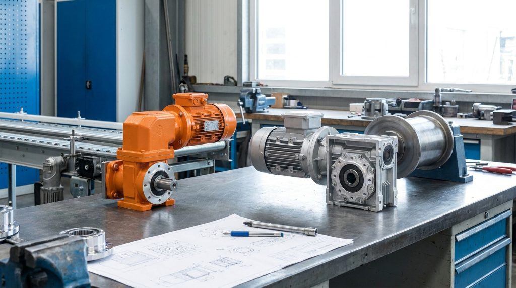
Understanding Gear Reducers: A Critical Component in Industrial Operations
Gear reducers, also known as gearboxes or speed reducers, are indispensable components in a vast array of industrial applications. Their primary function is to alter rotational speed and torque, enabling machinery to operate efficiently and effectively. Whether it’s driving conveyor belts in a manufacturing plant, powering agricultural equipment, or ensuring precise movement in complex automated systems, the right gear reducer is crucial for optimal performance, longevity, and safety. For businesses in Coldwater, Michigan, and beyond, understanding the nuances of different gear reducer types, particularly the distinction between right-angle vs. inline gear reducers, is fundamental to making informed purchasing and maintenance decisions. This article will delve into these critical differences, exploring their operational principles, typical applications, selection criteria, and the importance of expert service from providers like CEM Industrial Supply.
When considering the differences between right-angle and inline gear reducers, it’s also important to understand how these components interact with various materials and processes in industrial applications. For instance, the choice of gear reducer can significantly impact the efficiency of operations involving metalworking, such as those discussed in the article on selecting the right abrasive for metal, steel, and stainless materials. To explore this topic further, you can read the article here: How to Choose the Right Abrasive for Metal, Steel, and Stainless.
The Mechanics of Torque and Speed Reduction
At its core, a gear reducer’s purpose is to trade speed for torque, or vice versa, according to the principle of conservation of energy. When a higher-speed, lower-torque input shaft drives a gear reducer, the output shaft rotates at a slower speed but with a proportionally higher torque. This is achieved through a system of meshing gears. The gear ratio, defined as the ratio of the input gear’s teeth to the output gear’s teeth, dictates the extent of speed reduction and torque multiplication. A higher gear ratio signifies a greater reduction in speed and a greater increase in torque.
For example, a 10:1 gear ratio means the output shaft will rotate one-tenth the speed of the input shaft, but will have approximately ten times the torque (minus efficiency losses). This fundamental principle allows engineers to match the power output of a motor to the specific requirements of driven equipment. High-speed electric motors, for instance, are often paired with gear reducers to provide the necessary low-speed, high-torque output for heavy-duty machinery.
The efficiency of a gear reducer is a critical factor in energy consumption and operational cost. Losses occur due to friction between gear teeth, bearing friction, and oil churning. Different types of gear reducers and lubrication methods contribute to varying efficiency levels. Understanding these mechanical principles is the first step in appreciating why the physical configuration—inline versus right-angle—significantly impacts their suitability for specific tasks.
Inline Gear Reducers: Direct Power Transmission
Inline gear reducers are characterized by their input and output shafts being collinear, meaning they lie on the same straight line. This arrangement offers a compact and direct power transmission path, minimizing shaft misalignment issues and simplifying mounting in many scenarios. The power flows directly through the center of the gear reducer.
Types of Inline Gear Reducers
Several common types of gear arrangements are employed within inline gear reducers:
- Spur Gear Reducers: These are perhaps the simplest and most common type. They utilize cylindrical gears with teeth cut parallel to the axis of rotation. Spur gears are cost-effective, easy to manufacture, and offer high efficiency when properly aligned. Their primary drawback is that they can be noisy at high speeds and generate thrust loads that need to be managed.
- Applications: Conveyor systems, packaging machinery, washing machines, and general industrial machinery where noise is not a primary concern and shaft alignment is straightforward.
- Helical Gear Reducers: Helical gears have teeth cut at an angle to the axis of rotation. This angled tooth design results in more gradual engagement between gear teeth, leading to smoother and quieter operation compared to spur gears. They can also handle higher torque loads and are more durable. However, the helical teeth create axial thrust, which requires appropriate thrust bearings.
- Applications: Industrial fans, pumps, machine tools, and any application requiring high torque, smooth operation, and a quieter environment than spur gears can provide.
- Planetary Gear Reducers: These advanced reducers offer a compact and high-torque-density solution. They consist of a central sun gear, several planet gears that orbit the sun gear, and an outer ring gear. The input shaft typically drives the sun gear, and the output is taken from the planet carrier. This arrangement allows for high gear ratios in a small volume and provides excellent load sharing among multiple gears.
- Applications: Robotics, servo-driven applications, electric vehicles, and high-precision machinery where compact size, high torque, and precise control are paramount.
- Worm Gear Reducers: Worm gear reducers feature a screw-like input gear (the worm) that meshes with a gear wheel (the worm wheel). This configuration typically offers very high gear ratios in a single stage and is often self-locking, meaning the output shaft cannot be back-driven by the load. However, they are generally less efficient than spur or helical gears, and can generate significant heat.
- Applications: Lifting equipment, conveyors, gate operators, and any application requiring high reduction ratios and a self-locking mechanism.
Advantages of Inline Gear Reducers
- Simplicity and Cost-Effectiveness: Especially in spur and helical configurations, inline reducers are often simpler to design, manufacture, and maintain, leading to lower initial costs.
- High Efficiency: Spur and helical inline reducers generally offer high mechanical efficiency, minimizing energy waste.
- Compact Design: For applications where space is limited and direct drive is feasible, inline reducers can be very space-efficient.
- Ease of Mounting: Their collinear shaft design can simplify mounting and alignment, reducing installation complexity.
Disadvantages of Inline Gear Reducers
- Limited Orientation Flexibility: The collinear shaft requirement can limit mounting options in certain layouts.
- Potential for Noise: Spur gear variants can be noisy at higher speeds.
- Thrust Loads: Helical gears produce axial thrust that must be accommodated by the bearing system.
Right-Angle Gear Reducers: Navigating Directional Changes
Right-angle gear reducers, as their name suggests, are designed to change the direction of rotation by 90 degrees. This is achieved through specific gear configurations that redirect power flow from the input shaft to a perpendicular output shaft. This capability is invaluable in applications where the prime mover (motor) cannot be directly aligned with the driven equipment due to space constraints or functional requirements.
Types of Right-Angle Gear Reducers
The most common types of right-angle gear reducers are:
- Bevel Gear Reducers: These utilize bevel gears, which are conical in shape with teeth cut on their surface. When two bevel gears mesh, they transmit power at a 90-degree angle. The ratio of the number of teeth on the two gears determines the speed reduction.
- Applications: Automotive differentials, industrial mixers, material handling systems, and any application requiring a 90-degree power transmission.
- Worm Gear Reducers (often configured for right-angle output): While worm gears themselves can achieve right-angle transmission, they are typically categorized separately due to their unique operating principle. As mentioned earlier, they provide high reduction ratios and self-locking capabilities. The worm (input) engages the worm wheel (output) at a right angle.
- Applications: Conveyor systems, elevators, stairlifts, and any application where a high reduction ratio and 90-degree output are needed, along with the self-locking feature.
- Spur/Helical Gear Combinations with Idler Gears: While less common for primary right-angle transmission, some complex designs might incorporate spur or helical gears with an idler gear arrangement to achieve a 90-degree output. However, dedicated bevel or worm gear configurations are more efficient and common for this purpose.
Advantages of Right-Angle Gear Reducers
- Directional Flexibility: The primary advantage is their ability to redirect power flow, enabling more versatile machine design and layout.
- Space Saving: They can allow for more compact machine designs by placing the motor in a different orientation than the driven component.
- Torque Multiplication and Speed Reduction: Like inline reducers, they effectively multiply torque and reduce speed.
- Self-Locking (Worm Gear Type): The inherent self-locking property of worm gear reducers provides safety and control in applications where back-driving is undesirable.
Disadvantages of Right-Angle Gear Reducers
- Lower Efficiency: Bevel and especially worm gear reducers generally have lower mechanical efficiency compared to their inline spur or helical counterparts due to sliding friction and more complex meshing.
- Higher Cost: The more complex gearing and manufacturing processes can lead to a higher initial cost.
- Heat Generation (Worm Gear): Worm gear reducers can generate significant heat, requiring appropriate cooling or ventilation measures.
- Maintenance Complexity: The lubrication and maintenance of right-angle gear reducers, particularly worm gears, can be more intricate.
When exploring the differences between right-angle and inline gear reducers, it’s also beneficial to consider how these components impact overall system efficiency. A related article that delves into the advantages of various gear configurations can provide further insights into selecting the right reducer for your application. For more information, you can read about it here. Understanding these distinctions can help in making informed decisions that enhance performance and reliability in mechanical systems.
Key Differentiators: Choosing Between Right-Angle and Inline
The decision between an inline gear reducer and a right-angle gear reducer hinges on several critical factors specific to your application’s requirements.
Shaft Alignment and Space Constraints
The most fundamental difference is shaft alignment. If your motor and driven equipment are perfectly aligned, an inline reducer is often the more efficient and cost-effective choice. However, if space constraints, operational design, or component placement necessitate a perpendicular arrangement, a right-angle reducer becomes essential. For instance, a conveyor belt that needs to be elevated might utilize a right-angle reducer to position the motor above or below the belt’s path.
Efficiency and Power Loss
Inline helical and spur gear reducers typically boast higher efficiencies (often 90-98%) than right-angle reducers. Right-angle bevel gears might achieve 85-95% efficiency, while worm gears can range from 50% to 90%, depending on the ratio and specific design. This difference in efficiency translates directly to energy consumption and operational costs over time. If minimizing energy loss is a top priority, and an inline configuration is possible, it’s generally the preferred choice.
Torque Requirements and Gear Ratios
Both types of reducers can achieve high torque multiplication and speed reduction. However, the typical methods differ. For very high single-stage reduction ratios and self-locking capabilities, worm gear reducers (often used in right-angle configurations) are a strong contender. Planetary reducers (inline) are excellent for achieving high torque density in a compact package. Bevel gears are effective for right-angle transmission but might require multiple stages for extremely high reduction ratios.
Noise and Vibration
Inline helical gearboxes are renowned for their quiet and smooth operation due to the gradual engagement of their angled teeth. Spur gears, while efficient, can be noisier. Right-angle bevel gears are generally smoother than spur gears but can still generate some noise. Worm gears are typically quieter than spur gears but can produce a distinct whine. If noise levels are a critical concern, helical inline reducers often provide the best solution.
Cost Considerations
Generally, inline spur gear reducers are the most economical option. Helical inline reducers are moderately priced. Right-angle bevel gear reducers tend to be more expensive than inline helical units, and worm gear reducers can vary significantly in price, often being more costly for higher performance or specialized designs. The total cost of ownership, including energy consumption and maintenance, should be factored into this comparison.
Maintenance and Lubrication
The maintenance requirements can differ. Inline helical and spur gear reducers typically involve regular oil changes and seal checks. Worm gear reducers, due to higher operating temperatures and potential for wear, may require more specialized lubrication and more frequent monitoring. Understanding the specific maintenance needs of each type is crucial for long-term operational reliability.
Application-Specific Needs
- Manufacturing Automation: Inline reducers (especially planetary and helical) are common in precise automation where speed and torque control are critical.
- Material Handling: Both inline (conveyors) and right-angle (lifts, inclines) reducers are extensively used.
- Agriculture: Right-angle reducers are often found on PTO shafts for implements, while inline reducers might power augers or conveyors on processing equipment.
- Food Processing: Cleanliness and washdown capabilities are paramount. Specialized stainless steel inline or right-angle reducers are often specified.
When exploring the differences between right-angle and inline gear reducers, it’s also beneficial to consider their applications in various industries. For instance, a related article discusses the range of equipment available for rent, which can include gear reducers among other essential machinery. You can read more about this in the article found here. Understanding the specific requirements of your project can help you choose the right type of gear reducer for optimal performance.
Selection Criteria: Ensuring the Right Fit for Your Operation
Selecting the appropriate gear reducer is a critical engineering decision that impacts equipment performance, lifespan, and operational costs. For plant managers, maintenance professionals, and equipment buyers, a systematic approach is essential.
Technical Specifications: The Foundation of Selection
- Input Speed (RPM): The rotational speed of the motor or prime mover.
- Output Speed (RPM): The required speed of the driven equipment. This, combined with input speed, determines the gear ratio.
- Output Torque (in-lbs or Nm): The rotational force required by the driven load. This is a critical parameter that must be met or exceeded. Consider both continuous and peak torque requirements.
- Service Factor: A multiplier applied to the rated torque to account for the type of load (e.g., uniform, moderate shock, heavy shock), hours of operation per day, and starting frequency. Using an appropriate service factor ensures the reducer can withstand the actual operating conditions.
- Mounting Orientation: Will the reducer be mounted horizontally, vertically, or at an angle? This dictates the lubrication and sealing requirements.
- Operating Environment: Temperature extremes, presence of dust, moisture, chemicals, or corrosive elements. This influences material selection, sealing, and protection ratings (e.g., IP ratings).
- Power (HP or kW): The power rating of the motor.
Beyond the Basics: Advanced Considerations
- Duty Cycle: Continuous, intermittent, or short-time operation.
- Noise Levels: Particularly important in human-occupied spaces or sensitive environments.
- Vibration: High vibration can lead to premature wear and failure.
- Backlash: The amount of rotational play between meshing gears. Critical for precision applications like robotics.
- Thermal Capacity: The ability of the reducer to dissipate heat generated during operation. This is especially important for high-torque or high-ratio applications.
- Efficiency: As discussed, a crucial factor for energy consumption.
- Corrosion Resistance: For food processing, chemical plants, or outdoor applications.
- Special Features: Self-locking, integrated braking, specific shaft configurations.
Example: Selecting a Gear Reducer for a Conveyor Belt
Let’s consider a conveyor belt application.
- Determine Load Requirements:
- Load Weight and Speed: Calculate the required torque to move the load at the desired belt speed.
- Starting Load: Account for the torque needed to overcome inertia and static friction when starting. This often dictates a higher service factor.
- Motor Specifications:
- Motor Speed: Typically 1750 RPM or 1160 RPM for standard AC motors.
- Motor Power: Based on the load requirements.
- Gear Ratio Calculation:
Gear Ratio = Input Speed / Output Speed- If the motor runs at 1750 RPM and the belt needs to move at 50 RPM, the required ratio is
1750 / 50 = 35:1.
- Service Factor: If the load is moderate shock and runs 16 hours a day, a service factor of 1.5 or higher might be appropriate.
- Configuration:
- If the motor can be mounted inline with the conveyor shaft, an inline helical reducer with a 35:1 ratio would be a strong candidate for efficiency and quiet operation.
- If the motor must be mounted above the conveyor, a right-angle reducer (e.g., a worm gear reducer with a 35:1 ratio) might be necessary, accepting the lower efficiency for the layout flexibility.
Table 1: Gear Reducer Selection Checklist
| Parameter | Critical for Decision? | Notes |
| :– | : | : |
| Input Speed (RPM) | Yes | Motor speed. |
| Output Speed (RPM) | Yes | Desired driven equipment speed. |
| Required Output Torque | Yes | Continuous and peak torque. Crucial for sizing. |
| Service Factor | Yes | Accounts for load type, duty cycle, and operating conditions. |
| Mounting Orientation | Yes | Inline, right-angle, horizontal, vertical. Affects lubrication. |
| Ambient Temperature | Yes | Influences lubricant choice and cooling needs. |
| Contamination Level | Yes | Dust, moisture, chemicals; dictates sealing and material choice. |
| Noise Requirements | Often | Critical for operator comfort and regulatory compliance. |
| Efficiency Target | Often | Impacts energy costs and environmental footprint. |
| Backlash Tolerance | If applicable | Critical for precision motion control. |
| Budget | Yes | Initial cost vs. total cost of ownership. |
| Available Space | Yes | Dictates inline vs. right-angle and overall physical size. |
Troubleshooting and Maintenance: Extending Equipment Life
Proper maintenance is paramount to ensuring the longevity and reliable operation of any gear reducer, whether inline or right-angle. Proactive measures can prevent costly downtime and premature failure.
Common Gear Reducer Problems and Solutions
- Overheating:
- Causes: High load, insufficient lubrication, blocked cooling fins, incorrect oil viscosity, excessive ambient temperature, worn bearings.
- Solutions: Reduce load if possible, check and top up lubricant, ensure oil level is correct, clean cooling fins, verify oil viscosity, ensure adequate ventilation, and consider forced cooling for extreme conditions. If persistent, internal wear may be present.
- Excessive Noise and Vibration:
- Causes: Misalignment, worn gear teeth, bearing failure, loose mounting bolts, incorrect lubrication.
- Solutions: Check and correct shaft alignment. Inspect gears for wear or damage. Check bearings for play or roughness. Tighten mounting bolts. Ensure correct lubricant is used and at the proper level.
- Oil Leaks:
- Causes: Worn seals, damaged housings, improper seal installation, thermal expansion, overfilling.
- Solutions: Replace worn seals promptly. Inspect housings for cracks or damage. Ensure seals are installed correctly. Avoid overfilling lubricant. For extreme temperature fluctuations, consider breather vents.
- Gear Wear or Damage:
- Causes: Contaminated lubricant, overload, poor lubrication, misalignment, shock loads.
- Solutions: Identify and eliminate the root cause (e.g., improve filtration, reduce load, correct alignment). Gear damage often requires repair or replacement of the gear set.
- Bearing Failure:
- Causes: Contamination, improper lubrication, overload, shock loads, misalignment.
- Solutions: Replace bearings promptly and thoroughly clean the housing. Investigate the root cause to prevent recurrence.
Preventive Maintenance Schedule
A well-structured preventive maintenance program is key. For most industrial gear reducers, this includes:
- Regular Visual Inspections: Check for leaks, unusual noises, vibrations, and external damage.
- Lubricant Level Checks: Verify lubricant levels frequently, especially in units with sight glasses.
- Lubricant Sampling and Analysis: Periodically sample the lubricant and have it analyzed for wear metals, water contamination, and viscosity degradation. This can predict potential failures long before they occur.
- Oil Changes: Follow the manufacturer’s recommended interval, which depends on operating conditions and lubricant type. Consider more frequent changes for severe applications.
- Seal Inspections: Check seals for signs of wear or leakage during scheduled maintenance.
- Filter Changes (if applicable): If the reducer has an external filtration system, maintain it according to the manufacturer’s recommendations.
Importance of Expert Repair and Rebuilding Services
When gear reducers experience significant wear, damage, or failure, a professional repair and rebuilding service is often the most cost-effective and reliable solution compared to outright replacement. At CEM Industrial Supply, we specialize in industrial gearbox repair and rebuilding for a wide range of units. Our experienced technicians can diagnose issues, source quality replacement parts, and perform precise repairs to restore your gear reducer to its optimal performance. This includes:
- Thorough Disassembly and Inspection: Identifying all worn or damaged components.
- Precision Machining: Repairing or replacing shafts, housings, and gear sets.
- Bearing and Seal Replacement: Using high-quality components.
- Gear Set Replacement or Repair: Restoring proper meshing and function.
- Rigorous Testing: Ensuring the repaired unit meets or exceeds original specifications.
When to Consider Custom Solutions
While standard inline and right-angle gear reducers are suitable for many applications, some unique operational challenges or design requirements may necessitate custom solutions. CEM Industrial Supply can assist in developing and manufacturing custom gear reducers.
Scenarios Requiring Customization
- Unique Gear Ratios: When standard ratios do not precisely match the desired output speed or torque.
- Specialized Mounting Configurations: If standard mounting patterns do not fit the equipment’s frame or space.
- Extreme Operating Environments: High-temperature, corrosive, or vacuum applications may require specialized materials, seals, and lubricants.
- Unusual Input/Output Shaft Configurations: Non-standard shaft diameters, lengths, or keyways.
- Integrated Features: Combining a gear reducer with other components like brakes, clutches, or encoders within a single unit.
- Compact or High-Power Density Needs: Designing for maximum torque output within minimal physical space.
The CEM Industrial Supply Advantage
Our team of engineers and technical experts works closely with clients to understand their specific needs. We leverage our extensive knowledge of gear design and manufacturing to develop bespoke solutions that precisely meet performance, reliability, and integration requirements. Whether it’s modifying an existing design or creating a completely new unit, CEM Industrial Supply is equipped to deliver.
Conclusion: Partnering with CEM Industrial Supply for Your Gear Reducer Needs
The choice between right-angle and inline gear reducers is a foundational decision in industrial equipment design and operation. Understanding their distinct mechanical principles, advantages, disadvantages, and suitability for various applications is crucial for optimizing performance, efficiency, and longevity. From direct power transmission in inline configurations to the directional versatility of right-angle units, each plays a vital role.
For manufacturers, agricultural operators, plant managers, and maintenance professionals in Coldwater, Michigan, and across the region, ensuring the correct selection, installation, and maintenance of gear reducers is paramount. When facing challenges with existing equipment, unexpected failures, or the need for specialized solutions, CEM Industrial Supply stands ready as your trusted partner.
We offer comprehensive industrial gearbox repair and rebuilding services, breathing new life into worn or damaged units and saving you the significant cost of replacement. Our expertise ensures that your repaired gear reducers meet stringent performance standards. Furthermore, for applications with unique demands, we excel in providing custom-built gear reducer solutions tailored to your exact specifications.
Don’t let gear reducer issues hinder your operations. Contact CEM Industrial Supply today to discuss your industrial gearbox repair, rebuilding, or custom solution needs. Our team is dedicated to providing the expertise and reliable service you depend on.
Frequently Asked Questions (FAQs)
Q1: What is the primary difference between right-angle and inline gear reducers?
The primary difference lies in their shaft orientation. Inline gear reducers have collinear input and output shafts, meaning they lie on the same straight line. Right-angle gear reducers, conversely, are designed to change the direction of power transmission by 90 degrees, with the output shaft perpendicular to the input shaft.
Q2: Which type of gear reducer is more efficient: right-angle or inline?
Generally, inline gear reducers, particularly those using helical or spur gears, are more efficient than right-angle gear reducers. This is due to the simpler gear meshing and reduced sliding friction. Right-angle reducers, especially worm gear types, often have lower efficiency due to the nature of their gear interactions, which can lead to higher energy consumption.
Q3: When would I choose a worm gear reducer for a right-angle application?
You would typically choose a worm gear reducer for a right-angle application when you need a very high gear ratio in a single stage, and importantly, when the self-locking feature is desirable. This self-locking characteristic prevents the output shaft from being back-driven by the load, which is crucial for safety in applications like hoists, lifts, or certain types of conveyors.
Q4: How do I determine the correct service factor for my gear reducer?
The service factor is a multiplier used to account for the type of load (e.g., uniform, moderate shock, heavy shock), the number of hours the equipment operates per day, and the frequency of starts and stops. Manufacturers provide charts and guidelines to help you select the appropriate service factor based on your specific application’s operating conditions. Using an incorrect service factor can lead to premature failure.
Q5: What are the signs that my industrial gearbox needs repair or rebuilding?
Common signs include excessive noise (grinding, whining), increased vibration, overheating, visible oil leaks, a significant decrease in performance (reduced torque or speed), and visible wear or damage on external components. Regularly scheduled maintenance, including oil analysis, can help identify potential issues before they become critical failures.